PUSHBUTTON
Circuit
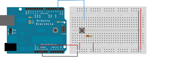
Connect three wires to the Arduino board. The first two, red and black, connect to the two long horizontal rows on the side of the breadboard to provide access to the 5 volt supply and ground. The third wire goes from digital pin 2 to one leg of the pushbutton. That same leg of the button connects through a pull-down resistor (here 10 KOhms) to ground. The other leg of the button connects to the 5 volt supply.
When the pushbutton is open (unpressed) there is no connection between the two legs of the pushbutton, so the pin is connected to ground (through the pull-down resistor) and we read a LOW. When the button is closed (pressed), it makes a connection between its two legs, connecting the pin to 5 volts, so that we read a HIGH.
You can also wire this circuit the opposite way, with a pullup resistor keeping the input HIGH, and going LOW when the button is pressed. If so, the behavior of the sketch will be reversed, with the LED normally on and turning off when you press the button.
If you disconnect the digital i/o pin from everything, the LED may blink erratically. This is because the input is "floating" - that is, it will randomly return either HIGH or LOW. That's why you need a pull-up or pull-down resistor in the circuit.
Code
(The following code turns on and off a light emitting diode (LED) connected to digital
pin 13, when pressing a pushbutton attached to pin 2. )
(The following code turns on and off a light emitting diode (LED) connected to digital
pin 13, when pressing a pushbutton attached to pin 2. )
|
const int buttonPin = 2;
const int ledPin = 13; int buttonState = 0; void setup() { pinMode(ledPin, OUTPUT); pinMode(buttonPin, INPUT); } void loop(){ buttonState = digitalRead(buttonPin); if (buttonState == HIGH) { digitalWrite(ledPin, HIGH); } else { digitalWrite(ledPin, LOW); } } |
the number of the PushButton pin
the number of the LED pin variable for reading the pushbutton status initialize the LED pin as an output: initialize the pushbutton pin as an input: read the state of the pushbutton value: check if the pushbutton is pressed. if it is, the buttonState is HIGH: turn LED on else turn LED off |
